Showing posts with label Raspberry PI. Show all posts

Tuesday, December 23, 2014

Robot Accidents will Happen

Things have been moving slowly forward. For a while there, I ran short on funding and without a constant supply of new parts, progress is slow. The last time I posted, I was talking about installing the head on K9. Well I got the head installed but there was some tragedy that followed the installation. I could not resist road testing him after installing his head and this was a mistake.

There must be a bug in his drive Arduino code that interprets the remote control signals for the wheels because as soon as I turned on my remote control unit, he decided to go into a spin. The failsafe I built into the code which shuts the motors down if a toggle switch on the remote is flipped also failed. Because he has two scooter motors, when he spins it can get very fast and I was not prepared. He spun so fast that when his head collided with a table leg, he broke his newly installed neck. This was a setback and I had to remove the existing neck hinge and start over. I don't think I will include any pictures of the lolling broken head. I have attached a temporary neck joint while I work out a more permanent way to rebuild it.

On a more progressive note, I have installed the Thermo Electric Printer into the head. I discovered that this printer is surprisingly versatile after a bit of a rocky start. When I would do anything other than a simple test print, the speakers attached to the Raspberry PI would literally growl and buzz as the printouts came out. If you listen closely during the video below you can hear strange, almost futuristic printing sound during the print process.


This cool sound was actually caused by a voltage drop from the Raspberry PI's power supply. I had hooked the printer's power and ground to the PI's +5 volt supply and it could not handle printing directly. When the printer drew too much power from the PI, it would literally stop printing. It also caused the PI to occasionally lock up as well. The solution was, of course, to get power directly from the battery and only drive the serial data from the PI. Here is a shot of the printer installed inside the head.

I had to actually saw of about 1cm from each side of the printer to get it to fit in the space available but fortunately, it was vestigial plastic and the printer still works. Once I got the printer working reliably, I was able to get it to print dithered photographs of faces and I expect I will be able to use it to print out souvenir print-outs with pictures of people's faces taken from the head mounted camera.

Next, I needed to create the red eye lens for the head. I purchased one 12" square sheet of red acrylic from Amazon and I started out using an acrylic cutting tool which turned out to be very slow and painful. I switched to a box cutter and even this was not very efficient. Finally, I just started using an electric Jig Saw and started cutting the stuff like wood. This works great as long as you go slowly. I think the blade actually melts a little as it cuts. Here is a shot of the end result.


In this shot you can also see the Raspberry PI camera which will eventually be mounted behind the red acrylic lens. You can also see the finished nose cover which was made by glueing a wooden dowel that was cut on an angle to the nose cover.

Now, I needed a way to create the eye lights behind the lens. Ultimately, these lights are used as an animatronic effect and are lit when the robot is speaking. In reality, I will have to place the head camera behind this lens as well so some compromises will have to be made to functionality. The camera itself will peep through a small hole on the right hand side of the lens.

Here bad fortune was turned to my advantage. A few weeks prior to working on this head, I accidentally dropped an exterior, LED porch light while trying to install it in the back yard and broke both its glass lenses in the process. I had to go buy another but I salvaged the white ultra bright tri-LEDs inside. 


They run fine on 12 volt power and I had two of them. They were perfect for eyes. There are cheeper ways to get LEDs than destroying and expensive, outdoor light fixture, but it all worked out in the end. I built a light box out of white cardboard to house the new eyes. Here is shot of the finished light box.

When I test lit the eyes they looked pretty good. Note that I had to put translucent paper behind the red lens to diffuse the light. Here is what they looked like when I test lit them.
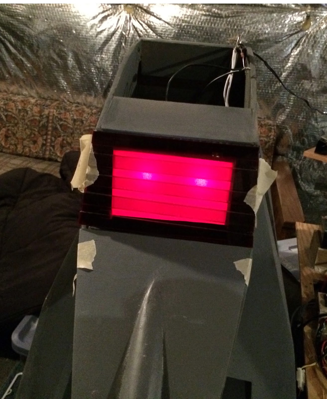

This photo does not really do them justice as it makes them look far brighter than they are.

I have made even more progress over the past few months but this entry is getting a little long so I am going to wrap things up. Next up, I will talk about how I relocated the Raspberry PI into the head and installed the electronic antenna and camera into the head as well. For now I will leave you with one more head shot of the completed, telescoping head antenna.


Progress is slow but steady. I am starting to look forward to the software side of this project since the hardware's completion is finally in sight.


Sunday, September 14, 2014

Getting A Head

I finally got around to building the head for my K9 prop/robot. I have been dreading this for a long time because of the rounded edges that are on the top, bottoms and sides of this piece. I knew there would be a lot of bending, scoring and clamping to make this happen. In the end, I was not 100% happy with the results. Let's start with a shot of the finished product.


The goal so far with body construction has been sand and prime the outer shell and move on. I intend to do a final patch sand and paint job at the end of the project after all the equipment has been fitted inside. 

At first I thought the head as too big but I have checked it against hero prop shots and the original plans and it's not. The production designers actually made the head bigger in later versions of the prop.  A fact I picked up while researching what I thought was a problem. It's a good thing it's big too because it needs to hold animatronics for its ears and nose and a thermal printer. I have also decided to move the raspberry PI and external speakers into the head as well to shorten the distance between it and the camera. The head will probably be more complex than the entire body. 

Now let's talk about construction. I started by gluing the bottom plate to the sides and then gluing a cross brace at the brow and the back of the head.

After clamping, I countersank wood screws on both sides of the cross braces. I later had to add a cross brace on the bottom because there was to much stress for glue alone to hold it together. 


Here is a shot looking down into the head from the top showing the bottom cross brace. This was after the brow cross brace and neck mount were inserted.

It is defiantly at an angle. His was because I adjusted it to try and change the shape of the head because it was a little mis-shapen without cross braces to hold it in place. Also shown here is a cross brace in the back of the head to allow the curved plate of wood in the back to be bent around it. 

The back plate had an almost circular curve to it. This is not easy to do with wood. I was thinking of using water to soften it but decided to score the back of it every inch and a half to make it more pliable. 
In the end this loosened it just enough to allow it to curve around the back just enough to fit. After this plate was attached I covered over all the screws with wood putty and gave everything a priming and sanding. 

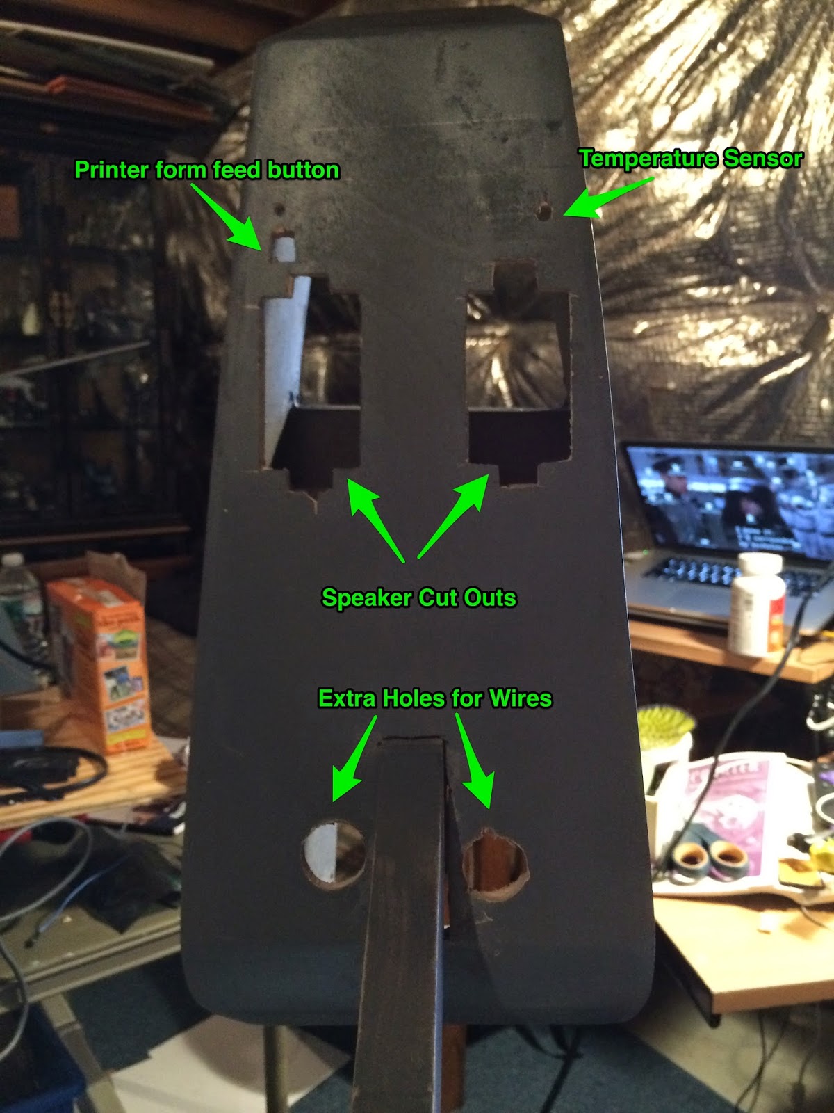
This left only the top of the nose and the head without wood. These will form the removable access doors. I will also have to cut additional compartments for speakers, printer controls and a temperature sensor. They are all going to be mounted on the underside as shown below.


I have fitted the head into place on the body to get a better idea how I am going to permanently mount it. During this process I discovered that once the head was installed, I could not longer use the remote control to move the robot forward. Its front mounted ultrasonic range finders kept reporting that there was an object about 8cm in front of it and it would not allow me to move it forward no matter what I did. I assumed that I had damaged the sensor while installing the head so I removed it.

Once I removed it, I could now move it by remote control. Unfortunately, without this sensor to stop it, once I started testing it, it ran out of control and broke its neck, causing the head to sag but not come completely off.  This is not my first setback during this project but it was the worst since the fire in the dorsal light control board. It was after this accident that I realize that the ultrasonic range sensor was detecting the robots own head as an obstacle. Once I moved the head up and out of the way, the range finder began working again. Pity I had to remove it and bench test it to find this out. I should have realized it when the problem first began.

Well this entry probably ran on too long so I will end it with a shot of K9 with his head (before it got broken) sitting next to Appa, the beagle. Next time I will talk about installing equipment into the newly build head.

Sunday, July 27, 2014

LCD Display and Tail Rig Installed

Its been a while since I updated. This is because progress is slow. I work on new hardware when I can. There have been significant improvements and I will summarize some of them with some progress pictures.

First off, my family has added a new real living dog to the crew. His name is Appa after the sky bison from Avatar: The Last Airbender. Here is a picture...


He is into everything and he is not sure what to make of K9. At least he has not decided to chew on him yet. Now back to what progress I have made.

In my last entry I had started working on the tail servo rig. This is now completed and I have a wagging tail that can be controlled through the web interface. Here is a video of the installed tail rig in operation.


The web interface is coming along nicely too. K9 runs a python based web server (Flask) and exposes all of his functions for debugging and testing through it. This has been invaluable as a testing tool, allowing me to debug the tail motor and dorsal lcd display. Here are a few shots of the web interface which is a work in progress, of course.


Moving on, I have finally gotten around to installing the LCD composite monitor on the left side of the shell. This is very handy because I can actually watch the boot-up process and know what is happening when things go wrong.


I still have the trim and an acrylic cover for this display on order which really needs to be installed so it will not look so obviously like a car dvd player. It still comes in really handy. Here is a video which shows off the display and the ability to play sounds from the web interface.


So everyone asks me, "That's great but when are you going to build the head?" Well its all about parts and time. I have the wood cut for the head but I don't want to assemble it until I at least get the printer that I am going to install in it delivered. I want to make sure I leave enough room inside the head to mount the printer. The head will have multiple servos inside it to control the ears, telescoping antenna and nose gun and will have to be constructed around these systems. Still, its next on the list and I need to get started on it.

I always like to post other K9 builds I come across. Here is one that I came across at Philadelphia Comicon this year (2014). I don't think it ever moved on its own and it obviously has been around (just look at the scratches and dents) but it is always interesting to see what other people have done.


Its a good reminder of how far I still have to go on this project to complete the hardware. After that, hopefully I will have even more work ahead of me writing software to allow it some autonomy from its own remote control. That's it for now, I will try to post some more design details and pictures as I start construction of the head.


Sunday, June 1, 2014

A Dog's Tail - Pitch and Yaw on the Cheap

I don't have the parts or tools to build rigs out of aluminum or steel but I need to figure out how a set of servos can control K9's tail. Wood and plastic will have to do for now until those parts break or wear out. The tail essentially is a pole that must be able to move horizontally and vertically by motor control. Here is a shot of the actual tail on the prop itself.


Fortunately, there are a few good examples already out there on how to build this motion rig. For example, here is one using only DC motors. Here is another example using Servo motors which is very impressive. This rig is built with multiple aluminum C-brackets and struts which looks very sturdy but I have no idea where to get the parts. So far I have built a test rig consisting of two RC aircraft 180 degree servo motors connected together, one to shaft of the other as seen in this example I found for sale.

Incidentally, if you are looking for the rubber fixture I am going to use, its a CV-Boot from a car. They can be found in almost any auto supply store. Here is a picture of the one I chose.


It is a close enough match to get the job done. I will end up cutting away the lower half when I mount it to the body. Now back to the test rig. Below is a video of the test rig I built just to see if my two server idea would work. The two servos are joined together with rubber bands so you will see a lot of oscillation as the arm moves around and a hanger is standing in for the antenna but other than that, it is performing the required motions.


Once I replace the rubber bands with firmer connections, all shaking will go away and I will have the wagging motions I need without having to construct a more complex rig. How long it will last in action will be another matter. Everything is being driven from an Arduino that is not connected to the main robot. This is just for testing purposes.  The next step will be to move everything to a permanent rig that I can attach to the CV-Boot inside the main shell. I will post pictures of that when that is completed.

Wednesday, May 7, 2014

A Dog Without A Head - K9 Assembly Testing

So this is another quick blog entry. Last night I did a test assembly of the main body, the dorsal control panel and the drive base. I just wanted to see how (and if) the parts fit together. This video features the new right side door which I will talk about more below.


For the longest time, I never bothered to manufacture a right, side door. This is where the classic K9 logo will go when the body is finished but up until now it was just a big access hole. The door needed to be custom fitted because even though it is draw out in the BBC plans, the body itself has a unique shape because it is built out of wood and glue as opposed to metal which would be far more rigid. I started with a cardboard test cut out which I roughly cut to fit and made adjustments on that. Then I duplicated this in particle board and spent quite a while sanding the edges until it just fit the hole.

It is interesting to point out that the lower portion of this door is angled down about 6 degrees to conform with the way the body itself is angled. Rather than cut and join two pieces of wood, I routed a horizontal line through the particle board along where the angle change occurs just thick enough to make the wood bendable. I then bent it into shape and filled the routed channel with plastic wood.


This turned out to work really well. The resulting door was a perfect fit and once it was sanded and sealed, looked like a natural bend in a single piece of metal.


This door will be held in place with four magnetic cabinet door catches so it will be secure but come off easily. You are also looking at the primed finish, not the final finish which I am waiting to apply until the entire body is complete. I will probably go with the dark blue metallic finish of the K9 Mk III as shown here when done.


Tuesday, May 6, 2014

Raspberry Hal

I wanted to keep a Raspberry PI running at my desk at work full time here at PTC but I wanted to have it out of the way. It would be available if I needed a system that remained at work while I was away with my laptop. I also wanted it as a test platform for some work I have just started doing on the ThingWorxs  platform and the "Internet of Things". Now you know me, I like to build electronics into science fiction replicas so I thought, why not build a Raspberry PI case into the polyurethane Hal replica I have hanging on my cube wall. Here is a shot of him from the day I put an Apple sticker on him before any modifications.

Unfortunately, he was made almost entirely out of solid, cast polyurethane. I tried to hollow him out with a Dremel tool but it was going to take a long time and be very messy because of the excessive dust it was generating. Because of this, I decided to recreate a hollow version of him in wood. I already had some experience creating control panels out of wood for my K9 project so I knew I could do a pretty convincing job. I had already installed a battery to light his eye and a light sensor on the polyurethane prop to turn the eye light off when the office was dark to conserve on battery power. I could reuse these in the new Hal.

For those of you who don't know much about Hal, he was the shipboard computer on the spacecraft Discovery One that tried to murder his entire crew when he felt they would interfere with his carrying out his mission in the movie 2001, A Space Odyssey. Here is a clip of him in action.


I wanted my new Hal to hold a Raspberry PI, some environmental sensors, an amplifier and his own speakers, all powered off of a single cell phone wall charger. He would be capable of playing appropriate Hal clips from the movie as well as responding to simple spoken commands. He should also serve as a Thingworx test platform for reporting metrics based off of the sensors I planed to install.

Here is a sentimental moment with Hal on my workbench saying his first words.


It was kind of creepy to hear him speak for the first time.

Here is the completed project now hanging on my cube wall. The prop has now been entirely rebuilt out of wood. He is fastened to the wall cloth with two pins that come out of the back of the unit at a 45 degree angle like a picture frame nail. This allows him to be easily removed for service.


One thing I did not expect was that when he is mounted flush to the wall, his temperature rises until he goes into thermal shutdown. It turns out that the PI generates so much heat that adequate ventilation is required. If there is no way for this heat to escape, the inside of the case can reach temperatures in excess of 50 degrees Celsius (122 degrees fahrenheit)! I had to bring him home and install four small legs that make him stand 1/4" back from the wall to allow for proper convection cooling. Now he stays at a cool 44 degrees C (111 degrees F).

Here is a shot of the back and side of the case with callouts for the parts inside. The only sensor I have installed so far was the original light sensor I took from the original polyurethane model I started with. I am adding a sound card (for speech recognition), external temperature sensor and an infra-red proximity sensor next. I will also replace the wire wrapping (the thin red wire nest) with a real cable.


I am planning on publishing the details of how to re-produce this project on Instructables soon along with the software running on the PI.


Tuesday, April 22, 2014

K9's Outer Shell - Building with Wood

Just ask my old shop teacher, I was never really gifted in the wood working department. Wood is the only material I am really at all familiar with, however, so that is what I will use to construct cosmetic parts for this robot. As I move forward with this project I am learning about other materials such as Vinyl, Aluminum and Acrylic but I basically have to stick with materials I can work with at home - so wood it is.

I mentioned in a previous blog entry that by first attempt a building the dorsal control panel was too small and I would have to build a new one. That gave me an opportunity to document the very an example of rudimentary techniques I used to construct the outer shell as I build this much smaller piece.

The first step usually is a cardboard model. In this case I was pretty sure what I wanted so I skipped this. Next step is drawing out the pieces onto a piece of wood. In this case, I am using very thin wood at only 1/8 of an inch. Here are the parts drawn into the wood.


You can see off to the right, the paper templates I printed out to transfer the lines onto the wood. Since this wood is only 1/8" thick, I then start to score the lines with an X-acto knife and then move to a box cutter. It helps to coat both side of the surface with clear packing tape before you do this to prevent the wood from splintering. Soon the wood will be cut through and you can remove the packing tape. If I were using 1/4 wood or particle board as I used in the frame I have show in past blogs, I would have to use a scroll saw or a bayonet saw to do the same thing. I then bored out the button holes by again covering the wood in clear packing tape and then using a 3/4" spade drill bit.

Next, thanks to the miracle that is Heavy Duty Liquid Nails I assembled and clamped the parts together. This piece has a curved section that will have to be clamped in place while the liquid nails drys.


Don't put on liquid nails to heavily as this severely increases the time required for it to dry. A light coat between the pieces will hold this thing together if you give it at least 24 hours to dry and set. I originally did not know how I was going to do the wood assembly this project would require but this stuff really holds things together.

After 24 hours has passed, I removed the clamps and Dremeled down the rough edges. Then I filled all the holes and remaining imperfections with Plastic Wood and sanded everything down smooth. Now it looks something like this.


Next, I had to cover up the wood grain. This is done by priming the wood and the standing down the primer coat until it fills the the wood grain.

Here is the near finished product. You can still see some wood grain but I am leaving it at this stage and moving on. I will do a final sanding and priming right before I do the final paint job once the entire body is finished.

I am going to postpone the final coat because until everything is finished, I am not sure what additional modifications I may need to do to the body before it is complete and I don't want to worry about marring the finish while work continues.

Here is the near finished product, sitting in the main body shell (Which, unfortunately, has some plastic wood filler on it at the moment) on the left compared to an actual shot of the detailed (hero) prop on the right. This time I have the correct scale.


Next, hooking the lights and switches back into the Arduino.

Friday, April 18, 2014

K9 Detects an Obstacle and Talks About It

This is very pre-mature but I have been working on generating events for the Raspberry PI which come from the Arduino as I have mentioned previously. Tonight was the first time I used one of these events. I have hooked up a temporary speaker and amplifier to the PI to allow it to play sounds. When the platform detects an obstacle using the Ping))) ultrasonic range finder, it stops the forward motor and sends an event to the PI. It responds by playing a sound. I thought the video was worth sharing.


The source for this interaction is available on my GitHub project but it has a long way to go.

Sunday, April 13, 2014

K9 Drive Base Demonstration

Things are progressing pretty well on the drive base. I have it configured to accept commands from both the on board Raspberry PI and an RC remote control. The remote control takes priority over any PI issued commands. This is useful if it should decide to do anything unexpected. When I first started testing it, I would put it up on blocks in case it decided to run away. Now I can flit the B switch on the remote control to stop it dead if this happens. Below is a picture of the current drive base with call outs that show what each component is.


It still looks like a bit of a rat's nest of wires but it is now capable of moving on its own and I can ssh over to the PI and give it commands like move forward or rotate around. Below is a video of my first tests. Excuse my weak voice, I have a bit of a cold.


As you can see it moves pretty fast. I have gone out of my way to restrict how fast it can go because when it is not carrying it external shell, it is far lighter than it will be when it is done. I already had one accident when my son was testing it out and he drove it hard into his own ankle and managed to hurt himself.

If you listen carefully you can also hear a high pitch noise whenever it moves. This is probably because the pulse width modulation frequency is too low and the motor itself is resonating in response to it. I will have to investigate changing that frequency to one outside the range of human hearing. Maybe, when I am done it will just annoy dogs.

Below is a head on shot. Here you can see the Parallax Ping))) sensor mounted on the front.


The speaker and microphone pair kind of look like eyes. If you look to the left you can see the RC receiver antenna which is being held on with a cable tie that looks a little like a sweat band. The ping sensor uses sound based radar to report obstacles up to 10 feet in front of it. These measurements are then passed on to the PI for further decision making.

At one point, I put the shell on and then got worried when the base refused to move forward. It would only go backward. Then I realized that when I had covered the Ping sensor, it was reporting that the shell was an obstruction in front of it and refused to move forward until the shell was removed.

Below is a shot of the two Razor scooters mounted to the bottom of the drive base. 


These scooter motors and rear wheels have been sawed off from the rest of the scooter. All that remains is the back 8 inches of the scooter. The rest was discarded. The frames are held to the mounting board with a U-bolt around the inner sides of the axels and three machine bolts that fit into the pre-drilled holes on the top of the frame and are very securely attached. There are also two wheels that spin freely and prevent the platform from tipping over.

You can also see that they are mounted in opposite directions. This is because the steel frames rapidly become wider than the base itself. If mounted in the same direction, they would be two wide to fit inside the shell. Having them face in opposite directions is not a problem because the DC motors can be rotated in either direction. If you look at the wiring diagram present in one of my previous posts, you will see that the left and right motors have their terminals reversed so as far as the controllers are concerned, they both move forward and backwards in unison.

Friday, April 11, 2014

Its Here! The new Printed Circuit Board Arrived.

You you may remember a few posts back, that the board I built to control the lights on the dorsal control panel on my K9 robot burned out because of a short. Well, the printed circuit board I designed to replace it has arrived. It took two weeks but for the price ($9.00 US) it was worth the wait for 5 copies of my design.


Thank you SeeedStudio. Yes, they have three eees in their name. Hopefully this weekend I can install the components and get it working.

Update: Here is a shot of it with all components installed.


This is the way to do it, all the holes were pre-tinned and all the traces are lacquered over. No more shorts.


Tuesday, April 8, 2014

Making K9 into a Pointer Dog - The HMC5883L Magnetometer

Real dogs have a breed called pointers which are also known as Gun Dogs bred to assist hunters in finding prey by pointing it out. I needed a similar capability to identify which direction the dive base is facing to stay on course while moving or for room mapping which is something I am interested in doing in the future.

I had never worked with a Magnetometer (Specifically the HMC5883L) and really did not know what to expect. They are fairly inexpensive to purchase. My first question was how to mount it. This may seem obvious but do you mount it flush or on its side? It turns out that the x-y plane provides the equivalent of a compass reading. If you look closely at your printed circuit board, there should be silk screened image of its three axis.
Your board may vary in size, color or number of pins but there should be an axis diagram. This one indicates that if you mount it flush with a horizontal surface and point the x-axis to the front, the angle between the vector formed by [x,y] and the centerline of your robot is the angle of your heading. I discovered this by reading the x and y values from the board as I rotated my robot base clockwise by hand. I graphed these points and repeated the process twice (the red and blue paths). 


The pink arrow represents the X axis and the direction of magnetic north which I found using a compass normal. As you can see, the points form an ellipse. I am no expert on this but I assume that the [x,y,z] vector represents the direction and the magnitude of the magnetic field at the point on Earth you are at. By looking at only the projection onto the x,y plane and then finding the center of the ellipsoid, you could calculate the angle between the x axis and the current [x,y] vector that points to magnetic north. Keep in mind all I know is what I have learned by experimenting with this board. If someone has any additional insight as to how this works, please pass it on. I am also ignoring any effects of tilting or z-axis data at this point. All I really wanted was my current angle from magnetic north but I was not getting this from the sample libraries a tried. I used the code at Adafruit to generate the x,y coordinates to create the graph above. You can see how its wired into my Arduino by looking at the diagram in my previous blog entry.

To calculate then center of this ellipse, I just placed a rectangle around it and then found the center of it as can be seen in the figure below. I calculated the center of the ellipse to be at (45,-360)
I don't know if this point will work for you or if this center will shift when I take the robot to new locations but for now I am using this as my center and I am getting fairly accurate readings on my heading relative to magnetic north.


Here, I calculate the angle between the current vector and the x axis which is the midline of my drive platform and then add or subtract from that angle to place it in the correct quadrant so so that I get the equivalent of a magnetic compass reading in degrees. My approach may be flawed as I mentioned above but I will update this post as I learn more about this device. The entire sketch that the gist above is taken from can be seen here. This sketch reads all the other devices listed in my previous blog entry and emits events over the USB bus to the Raspberry PI in JSON format indicating what the current heading is. I will talk about these events and the PI can send back to the Arduino in my next entry.

Monday, April 7, 2014

Making K9 Move - The motor base

I have been experimenting with building a base to sit my K9 outer shell on top of and things are really proceeding very well. For about $500.00 in parts I have created a platform that fits inside the shell that can be controlled either by a Raspberry PI or an RC remote control. Here is a picture of the platform with the parts I am planning on installing laid out on it but not yet connected. Here you can see the board that the scooters are attached two with plus shaped cut outs in the center to allow the wheels to pass through.


The platform consists of the following items.

1 1/4" Pine board with holes cut out for the wheels
2 Razor 24 Volt batteries (They come with the scooters, not shown above)
1 Terminal block
1 Raspberry PI
2  U-Bolts (1/4x1-1/8x3-1/2) used to attach the axel to the board
6 3/16x1 Washers
6 10-24 x3/4 Pan Phillips Machine screws which are the perfect size to screw through the wood into the steel frame.

Here is how the components are connected together.


If you look closely, you can spot that I have attached the scooters to the platform facing in opposite directions. This was to allow the steel frames to fit together closely enough to stay within the limits of the with of the board they were being mounted to. In the diagram above I have reversed the electrical connections to the motor to make both motors consistently move in the same direction. This could also be accomplished in code as well but this makes them both appear to be facing in the same direction as far as the controllers are concerned.

When working with high current systems it is a good idea to use heavier gage wire. I am using 18 gage stranded wire for all the motor connections which I am wiring into a terminal block for distribution. I have also wired the step down regulator into the terminal block to provide 3 amps of 5 volt service which should be enough to power two Ardunios and the PI.

Each scooter's specs state they can propel a child up to 10 mph for 40 minutes between charges. This platform packs two of them and will weigh far less so I am expecting really good performance. In addition the steel frames use a bicycle chain to transfer power from the motors to the polyurethane wheels. 

I put some thought into how I wanted the wheels arranged. I know I wanted four wheels, two powered and two idle to form a stable base that would not be easily tip-able. I also wanted the shortest possible turn radius as my goal was to develop autonomous navigation projects and having a near zero turn radius would allow the robot to maneuver in close quarters. This mean placing the wheels in the midsection of the body. By rotating them in opposite directions, the robot could literally spin around its z-axis, doing a complete 180° turn in place. I decided on a Hilare-type wheel arrangement which is a two wheeled differential drive with two additional passive points of contact (casters) was the way to make this happen.

After sawing away most of the scooter with a sawzall, only the back wheel and the motor remain. It turns out that using a combination of a large U-Bolt and 3 replacement screws listed above is all you need to anchor the scooter to the board. Here is a side shot of the mounted scooter frame.

I think I have been postponing posts because I want to put too much information into them so I am going to wrap this one up at this point and cover the communications protocol and how I am interpreting the sensor data as well as prioritizing remote control requests higher than PI requests in another post. I also want to talk about the power supply and how I want to manage battery charging. You can always look at the current state of my Arduino source code here. I have not yet started adding support for this peripheral to the PI daemon. It still has a long way to go.


Friday, March 28, 2014

A PCB for the K9 Dorsal Keyboard Driver

So, I mentioned that the driver board for controlling the dorsal keyboard panel shorted out on me. Well, I have decided to not rebuild it from a prototyping board but instead get a printed circuit board manufactured so this does not happen again. This way there is no chance of a home mead header pin folding over as the traces should be sealed and I will be using a real head block this time like the kind present on the Arduino.
I have only ever built home made printed circuit boards before. I have never used CAD software to create them and I have never designed a multi layer board before so this was quite an education. Here is a little bit about what I learned.

Seedstudio will manufacture five copies of a 2 layer 5x5cm board for around $10 by sending it out to China. I am in no hurry and this is a great price. Element 14 recommended  Sunstone Circuits who can do a single prototype for $40 and get it to you faster.

All of these manufacturing houses require something called Gerber Files which it turns out have nothing to do with baby food at all but are actually a set of documents that describe the layers of your board such as the silk screen, top layer, bottom layer, connections between layers (called vias) and where holes need to be drilled.

I needed a way to create these files and I discovered a free to use CAD program that will help you lay them our called Eagle. Eagle is not as simple to use as a lot of modern drawing software and harkens back to old unix workstation engineering packages a little bit but there are a great set of tutorials on how to use it by Jeremy Blum. This was pretty much all I needed to create the PCB board design shown above.

This board was pretty simple to design since all I really had to do was draw out the entire circuit diagram. 

From this, it created a sample PCB and I moved the components to where I wanted them to be located. Since this board does not carry any high frequency signals I did not really have to worry about shielding or bends in the tracing but the tutorial addresses these issues as well.  Next, it auto routed two layers of copper for me and then let me tweak the routes and add my own text to the silk screen layer. With the help of Jeremy's videos I rendered the gerber files and am about to place my order with Seedstudio. When the boards show up, I will talk more about how well the whole processes turned out.

I have placed my eagle project on git hub.

Monday, March 24, 2014

K9 Source Code Now Available

I have moved my source code from a private repository to a public on on github.com . Keep in mind that it is a work in progress and I think the most use it will have at this point is to provide me a way to link to source code I want to talk about in this blog. The source code can be found here.


What is currently in this repository is the Arduino code for the dorsal control panel and a Raspberry PI Python source for a daemon to control the Arduino and in turn the switches, light and LCD display. There is more than one way for a Raspberry PI to communicate with an Arduino (such as I2C) but I have chosen, at least initially, to use USB . The PI is the master decision maker based on messages it receives from the two Arduinos in the system. The Arduinos, in some cases, can simplify and filter the inputs into more meaningful messages to reduce traffic over the bus.

The format of the over the wire data is JSON. Even though there is no Javascript in use, I am just more comfortable reading and working with JSON. The Arduino has a JSON library (aJson by Marcus Nowotny) and so does Python so I am not in the business of parsing data, only interpreting it.

A simple set of commands and events has been created that allows the dorsal panel to be controlled and to emit keyup and keydown events. Here is an example.
{"lightcode":3} // Turns on the first two panel lights (ie 2^0+2^1 or 1+2)
{"backlighton":true} // Turns on the LCD backlight
{"line2":"Hello","line3":"World"} // Display the text hello on LCD display line 1 and world on line 2 
These commands can be typed to the Arduino's in the Serial Monitor for easy testing as well. You can take a look at the Arduino sketch in its current state here.

The Arduino emits JSON back to the PI to let it know when events such as key presses occur. Right now it generates events such as:
{"key8":"down"}
{"key12":"up"}
To process these events I am working on a python script that listens on the USB device representing the Arduino and connects the keydown events to light sequences on the control panel as a proof of concept. This script runs as a daemon started by the PI's init daemon when the PI boots up. Its job will be to coordinate button pushes with button lights and allow the user to make LCD menu choices.

Right now, individual buttons have been tied to lighting animations which makes for an interesting demo.

Alas, I demo-ed the light animations and had them trigger against different buttons on the keyboard a couple times but failed to make any videos.  I went to make a video just for this blog post and when a powered up the board, I had an expected short that seems to have burned out all the transistors. This is both a curse and a blessing. It is blessing because 1. it did not burn out the Arduino and 2. It gives me an excuse to create a PCB to replace it. I will talk about the PCB board creation process in a future entry and will update this entry in the future when I get the demo running again.

Friday, March 7, 2014

Building and Interfacing K9's Dorsal Control Pannel

This is one of the more complex components that has to created. I wanted it to be functional, not just a light show. By functional, I mean that these buttons should be able to be used to communicate with the Raspberry PI and it should be able to control them as well.

In addition to the twelve colored buttons, this panel also contains a red display, separated into two segments. I wanted this display to be backed by a multi line liquid crystal display. This display could act as a simple console like the kind often used in laser printers that lets you access its features. The buttons could act as a keypad to respond to menus presented on they keypad. This meant that I would have to make a change to the display from the original prop. I will be removing the segment in the middle.

Both the LCD and the twelve key keyboard will be controlled by their own Arduino. This arduino will communicate serially with the Raspberry PI. This will require analog pins A4 for data and A5 for the clock for I2C communication for the LCD display. We will also need 12 digital inputs to tell if a switch has been depressed and 12 digial output to actually light the lights in the switches. This is a problem as most Arduinos only have 13 digital i/o pins total. A shield will be required here to drive this board.

Enter the Numato Lab's IO Expander Shield. It will add 28 more digital i/o pins to our Arduino that will be I2C controlled as well. We now have our required 24 digital i/o lines with some to spare which we may want to use later.

I am assuming here that the dorsal control panel box has already been constructed from the plans I have linked to in past entries so lets talk about the hardware needed to create the LCD display and keyboard. Since I am basing my K9's drive system on electric scooters, I will have a 24 Volt primary power supply from the batteries taken out of the scooters. The lighted switches I need will require 24 volts to light up and will have to signal the Expander shield with a 24 Volt signal as well. What colors you want to use are up to you because I have found no consistency in any of the prop pictures. Here is a shot of the actual hero prop I got from the K9 builder's Site. I could not match the switches perfectly but I came pretty close.


Here is a parts list.

  1 Arduino Uno
  1 Numato Labs Digital and Analog IO Expander Shield
  1 SainSmart LCD Module For Arduino 20 X 4, PCB Board, White On Blue
12 2N2222 Transistors
12 2200 Ohm Resistors
12 1N4007 Diodes
12 100nF Capacitors
12 1K Ohm Resistors
12 4.7K Ohm Resistors
12 Panel Mount Momentary Assorted Colored Lamp Rectangular Push Button Switch DC 24V
  6 10 pcs Single Row (L 11MM) Male 1x40 Pin Header Strip 2.54 mm Pin Header
  5 40P 2.54mm Dupont Cable Female To Female 20cm For Arduino
  2 Solderable PC BreadBoard, 1 Sided PCB

I purchased everything off this list except the Numato board directly from Amazon but as this article ages, the links I have included may go bad so I have tried to include extensive descriptions as well.

You may also want to purchase a wire wrapping tool as well as pre made female to female cables work very well but some of the connections (like the ground and +24 volt busses) are easier to do with a wire wrap tool.

The LCD only needs to be hooked directly into the I2C Bus and Power. Here is a link to the specifications and test code for this display. Simply hook SDA(DATA)->A4,SCL(CLOCK)->A5, GND->GND, VCC->5V. Here is a sample project that shows how it is connected.

Now lets discuss the actual circuits that are required to drive the keyboard. To be able to light the lights inside each switch on demand they must be hooked up to D0-D11 of the Numato board. They cannot be directly connected because 5 volts is not enough to light the light and the Numato board can only supply 25 mA of current max. We need a circuit that will switch 36mA at 24 Volts from a signal under 25mA at 5 volts. It is shown below. 12 of them are required, one for each of the D0-D11 pins.


I built my first version of this board before I discovered the magic that is the Single Row Male 1x40 Pin Header Strip so you will see where my connection points are spread all over the board. Eventually, I will replace this with a home made printed circuit board. My prototype looks like this (left - in progress. right - complete) :

Next is the circuit for reading the state of all twelve switches and reporting them back to the Arduino. This circuit uses the 24 Volt power supply from the battery and switches it through voltage divider circuit. Basically, when you push the button down, you are delivering 1/5 of 24 volts to the digital input pin which places it in the range lower than 5 volts which is the maximum permitted to turn the digital pin to the on state and only requires about 4mA to operate a single switch when pressed. We will also be able to detect when multiple sets of switches are pressed as well. The capacitor is present to prevent the switch from bouncing. You will need one of these circuits to detect when each switch is depressed on the keyboard. 

Here is a picture of the finished product with only the d22 wire connected.


I am not crazy about the layout and I may have to put some hot glue in to stabilize the capacitors to prevent shorts but I really need to make this a printed circuit board anyway.

Shown below is some of the wiring in progress for the actual switches. All of the bulb positives and commons are all wired to 24 Volts +. This is shown below with wire wrap wire. The colored lines are the control signal to light the lights. The signal sent back to the Arduino indicating a switch has been pressed is yet to be connected to each Normally Closed (NC) terminal. These are wired into the printed circuit board shown above.


I have almost finished testing reading when a button has been pressed and forwarding that information back to my Raspberry PI. Once I do I look forward to implementing the game Simon just for fun, The software control of this keyboard is really a whole additional blog entry as it is somewhat complicated so I will save that for next time. In closing, here is the last self test I recorded which I used to make sure the lights are working.

Another thing you may have noticed is that my actual wooden shell for the control panel is too small compared to the actual picture of the real prop shown above. I am going to have to build another one a move all the part into it to correct this mistake. What is it they say, measure twice, cut once.