Friday, March 7, 2014

Building and Interfacing K9's Dorsal Control Pannel

This is one of the more complex components that has to created. I wanted it to be functional, not just a light show. By functional, I mean that these buttons should be able to be used to communicate with the Raspberry PI and it should be able to control them as well.

In addition to the twelve colored buttons, this panel also contains a red display, separated into two segments. I wanted this display to be backed by a multi line liquid crystal display. This display could act as a simple console like the kind often used in laser printers that lets you access its features. The buttons could act as a keypad to respond to menus presented on they keypad. This meant that I would have to make a change to the display from the original prop. I will be removing the segment in the middle.

Both the LCD and the twelve key keyboard will be controlled by their own Arduino. This arduino will communicate serially with the Raspberry PI. This will require analog pins A4 for data and A5 for the clock for I2C communication for the LCD display. We will also need 12 digital inputs to tell if a switch has been depressed and 12 digial output to actually light the lights in the switches. This is a problem as most Arduinos only have 13 digital i/o pins total. A shield will be required here to drive this board.

Enter the Numato Lab's IO Expander Shield. It will add 28 more digital i/o pins to our Arduino that will be I2C controlled as well. We now have our required 24 digital i/o lines with some to spare which we may want to use later.

I am assuming here that the dorsal control panel box has already been constructed from the plans I have linked to in past entries so lets talk about the hardware needed to create the LCD display and keyboard. Since I am basing my K9's drive system on electric scooters, I will have a 24 Volt primary power supply from the batteries taken out of the scooters. The lighted switches I need will require 24 volts to light up and will have to signal the Expander shield with a 24 Volt signal as well. What colors you want to use are up to you because I have found no consistency in any of the prop pictures. Here is a shot of the actual hero prop I got from the K9 builder's Site. I could not match the switches perfectly but I came pretty close.


Here is a parts list.

  1 Arduino Uno
  1 Numato Labs Digital and Analog IO Expander Shield
  1 SainSmart LCD Module For Arduino 20 X 4, PCB Board, White On Blue
12 2N2222 Transistors
12 2200 Ohm Resistors
12 1N4007 Diodes
12 100nF Capacitors
12 1K Ohm Resistors
12 4.7K Ohm Resistors
12 Panel Mount Momentary Assorted Colored Lamp Rectangular Push Button Switch DC 24V
  6 10 pcs Single Row (L 11MM) Male 1x40 Pin Header Strip 2.54 mm Pin Header
  5 40P 2.54mm Dupont Cable Female To Female 20cm For Arduino
  2 Solderable PC BreadBoard, 1 Sided PCB

I purchased everything off this list except the Numato board directly from Amazon but as this article ages, the links I have included may go bad so I have tried to include extensive descriptions as well.

You may also want to purchase a wire wrapping tool as well as pre made female to female cables work very well but some of the connections (like the ground and +24 volt busses) are easier to do with a wire wrap tool.

The LCD only needs to be hooked directly into the I2C Bus and Power. Here is a link to the specifications and test code for this display. Simply hook SDA(DATA)->A4,SCL(CLOCK)->A5, GND->GND, VCC->5V. Here is a sample project that shows how it is connected.

Now lets discuss the actual circuits that are required to drive the keyboard. To be able to light the lights inside each switch on demand they must be hooked up to D0-D11 of the Numato board. They cannot be directly connected because 5 volts is not enough to light the light and the Numato board can only supply 25 mA of current max. We need a circuit that will switch 36mA at 24 Volts from a signal under 25mA at 5 volts. It is shown below. 12 of them are required, one for each of the D0-D11 pins.


I built my first version of this board before I discovered the magic that is the Single Row Male 1x40 Pin Header Strip so you will see where my connection points are spread all over the board. Eventually, I will replace this with a home made printed circuit board. My prototype looks like this (left - in progress. right - complete) :

Next is the circuit for reading the state of all twelve switches and reporting them back to the Arduino. This circuit uses the 24 Volt power supply from the battery and switches it through voltage divider circuit. Basically, when you push the button down, you are delivering 1/5 of 24 volts to the digital input pin which places it in the range lower than 5 volts which is the maximum permitted to turn the digital pin to the on state and only requires about 4mA to operate a single switch when pressed. We will also be able to detect when multiple sets of switches are pressed as well. The capacitor is present to prevent the switch from bouncing. You will need one of these circuits to detect when each switch is depressed on the keyboard. 

Here is a picture of the finished product with only the d22 wire connected.


I am not crazy about the layout and I may have to put some hot glue in to stabilize the capacitors to prevent shorts but I really need to make this a printed circuit board anyway.

Shown below is some of the wiring in progress for the actual switches. All of the bulb positives and commons are all wired to 24 Volts +. This is shown below with wire wrap wire. The colored lines are the control signal to light the lights. The signal sent back to the Arduino indicating a switch has been pressed is yet to be connected to each Normally Closed (NC) terminal. These are wired into the printed circuit board shown above.


I have almost finished testing reading when a button has been pressed and forwarding that information back to my Raspberry PI. Once I do I look forward to implementing the game Simon just for fun, The software control of this keyboard is really a whole additional blog entry as it is somewhat complicated so I will save that for next time. In closing, here is the last self test I recorded which I used to make sure the lights are working.

Another thing you may have noticed is that my actual wooden shell for the control panel is too small compared to the actual picture of the real prop shown above. I am going to have to build another one a move all the part into it to correct this mistake. What is it they say, measure twice, cut once.

Monday, March 3, 2014

Is Apple Like A Chicken Without A Head?

I was reading the other day about Mike the Headless Chicken. Mike was one of a crop of Chickens that had their heads chopped off prior to being served up as someone's meal but unlike the other chickens, Mike didn't die.

Mike lived on far longer without his head than anyone though he could. His body lived on, was fed and actually traveled the world performing in side shows for 18 months after his decapitation. He was a miracle to behold because when he was decapitated, the farmer left most of his brainstem intact and that was all he needed to run his basic bodily functions. An amazing true story that I hope does not parallel Apple Inc's performance since the passing of Steve Jobs.

What got me thinking about this was trying to help someone with their iCloud notes synchronization of all things. Let me explain. I have been a Macintosh developer almost since the product was released. I got my first Mac in 1985 as part of the second crop of freshmen who received Macs as part of their school tuition at Drexel University. I dove right in and tried to learn everything I could about software development on the Mac. My first two full-time jobs after I graduated were both Mac development jobs. I was excited for the future.

What I did not realize at the time was that Steve had left Apple in 1985 and in retrospect, Apple had started to coast, much like Mike. Innovation has started to turn into incremental improvements. Stagnation had set in, most likely due to risk avoidance. The same kind of risk that Steve Jobs pursued during his tenure was diminishing every year.

Slowly, my day job turned from Mac development to Windows development. Customer demand for Windows products was up and Mac demand was down and I moved on, not really noticing the reasons for this shift at the time.

Now on to 2005. After spending years developing for Windows and becoming intimately familiar with its warts and bruises, I had moved on to pure Java development. After Apple's migration to Intel hardware I decided to take another peek at Apple computers. Performance on Power PC macs was lagging behind most Intel systems at that point and it looked like the time to see if this was a platform was now worth switching back to.

What I found was a reliable, engaging platform that was fast and gave me the kind of flexible command line that I could only find previously on Linux boxes. It was easy to use, much less troubled by viruses and did not slow down over time. I was back and times were good. I would tune in to Apple keynotes like Macworld in January and look forward to new innovations like the iPhone and iPad. These also brought with them new development challenges and endless new Apps. Times were good again.

Now I am beginning to wonder if the Mike analogy is appropriate again. Here is why. Remember MobileMe? I do. It was a disaster and Steve gave it the mercy killing it deserved. It was replaced by iCloud which I had a lot of hope for but this hope is fading in the light of competition and the lack of continued improvement or innovation. When I think about it, I use dropbox more, on Apple platforms than I ever use iCloud storage. iCloud is everywhere (on my Apple devices) but not anywhere else. Is free storage size is small and Dropbox is everywhere, on all platforms.

You might come back and say, "But it is so simple, I don't have to think about it." But you do. The first thing I noticed about iCloud synchronization is the annoying feature of having a local and cloud based store of information. You can have local calendars and notes that don't synchronize and it is easy to start using them, only to discover your stuff isn't everywhere. I know this is a feature but more than one person has come to me asking why their content is not syncing and the answer always is these local data stores. This is not something that should ever get turned on by default.

My other complaint about iCloud is it's app centric philosophy. Drop box just cares about files. I can put a file in it and its on all my devices. I don't ever have to think about it. When I go to iCloud.com I don't see my files, I just see apps that can edit them. I guess this is ok, but the test of time has proven to me that I want to see are my files because I keep falling back to dropbox. Just try to make a file public on iCloud so that anyone can download it. You just can't do it.

Next is iTunes. I pay my $20 a year for streaming privileges and when this feature came out it was half baked. It would fill my phone with streaming content to the point where I would have to delete my iTunes library just to install a new app. No one wanted it to work that way and they finally made it simple streaming. Time has moved on and now Google will stream all my music for free and will import my iTunes library anywhere. Where is my iTunes app on iCloud.com?  Its not there. Can I watched amy video I purchased there? No. When are they going to stop charging me $20 a year for something I can get for free. They probably won't stop. Things will just go on the way they are because nobody is going to make the same call Steve did with MobileMe.

The iPhone was amazing when it first came out. No other device could do what it could do. Every year it got better and better. I would expect innovation to slow down on this product eventually but all two quickly the changes became incremental. Now new phones are starting to populate the product line that don't really make sense. Did the iPhone 5c remind anyone of the days of the Macintosh Quadra's and Performas? A proliferation of a product line that just made no sense? Who wants to buy the second best new iPhone? It turned out no one did.

And what about Siri? It progresses painfully slowly. Born in the final Steve era, it still can be classified as useful when it feels like it. One day you can ask it something and it works and the next you can ask it the same thing and it fails. Don't ever try to use it without a good network connection because it just won't work. Google has caught up because it has advanced so slowly. There speech recognition is now better and from what I can tell, we are approaching the turning point for new software innovation transitioning from IOS to Android any day now.

I read Steve's authorized autobiography. One thing I remember is that he did not ever want anyone to ask themselves, "What would Steve do?", after he was gone. What they should ask is what is the next opportunity to innovate. Steve appointed Tim Cook, his former head of operations to replace him. I though this was an odd choice. I was hoping for someone more drastic or Mercurial. Operations is kind of like the brain stem of a company. It gets resources where they need to be and keeps the body moving smoothly. In general, Apple's stock price is still high. Innovation comes in small jumps. My iPhone now has a thumbprint scanner but Mike lived for 18 months before his body finally failed. Are we seeing the radical innovation we were used to or are we seeing the body live on without the head?

So now I find my self looking to the future. Will there be an iWatch? Will the AppleTV finally open itself up to Apps and Games? Where is the Apple brand TV that Steve mentions in his autobiography? Will we see something no one expected or will I find my next laptop is running Linux and I am developing for Android? I am waiting for a sign. I hope I see one soon. Can this chicken grow a new head?


My K9 Robot's Overall System Architecture

Nothing is set in stone yet but I have been thinking about this for a while and decided to map out what peripherals I will be including in this project. I have spent a lot of time building the shell but I am just starting to build the electronics that will integrate my Raspberry PI into it. Below is an overall map of the systems that will be connected to the PI.

Where possible, I try to include what resources they will use in terms of ports or pins and nothing is connected directly to the PI's GPIO as of yet. This may become necessary if USB access for sensor data is too slow.

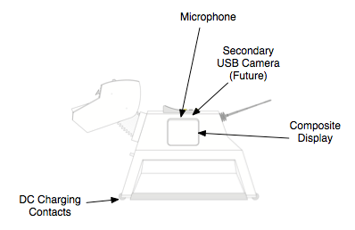
So where on the actual shell will these systems be located? Here are some callouts that will give you a general idea.

LEFT SIDE

RIGHT SIDE

FRONT/REAR

These diagrams come from the original BBC plans with my callouts added to show equipment location. I will attempt prevent these real life peripherals from altering the normal appearance of the original prop.

I have already constructed some of these peripherals including the dorsal control panel and LCD display which will need to have a post all its own when it is completed. Here is a short video showing it performing one of its first self tests.


Keep in mind that the surface of this piece has only been primed and will not show the rough line marks that a visible now when it is completed. Here you can see the display light individual lights by generating powers of 2^n as integers. It is capable of lighting any combination of the twenty four lights simultaneously. Once the switches are wired into the Arduino, I will be able to use them to interact with menus displayed on the LCD screen.

There is already as small body of Arduino sketch and python code which controls this control panel and I have been thinking about putting this on GitHub in the near future. I will also start including parts lists and diagrams which are probably to detailed to post in my blog in case anyone gets the idea to try this project themselves in the future.


Thursday, February 27, 2014

An Infra-Red Leash for an Electronic Dog?

One of the things I intend to implement is the ability for this robot to follow me or a target I designate. I was thinking about how I could implement this feature and thought I would just record my thoughts so far.

I had been planning on cannibalizing a WII remote at some point for its infra red camera. I did some looking around on the internet today and I found another useful Intructables project on how to extract the Wi Remote's infrared camera and the hardware that monitors it and connect it to an Arduino.  It then cranks out the x,y coordinates of the four strongest infrared sources it sees and makes them available to the Arduino.

One of the experiments I need to perform is to see if I can use this camera to track an infrared LED I could then wear one and have the robot follow me by attempting to center the x coordinate by rotating its body as it moved.

The distance from the center point of the display in y would be proportional to the distance from the target. If I had some idea as to the average distance from the floor the LED was mounted on the target I may even be able to calculate distance. At close range the LED may go outside the field of view anyway in which case you would have to assume you had reached the target.
I have not thought much yet about where on the robot to mount it. Would there be any advantage to placing it inside the head which can move up and down in the Y axis?

This camera has been used to create simple electronic whiteboards as well.  Perhaps I could also use it as an input device for drawing in the air or on a white board as well. Another interesting fact I did not know is that WII remotes use bluetooth to communicate and can be paired with any laptop with bluetooth build in. Bluetooth is not really an option for me since I don't want to add another radio if I can avoid it. I am already planning on using WIFI for remote control and internet access.

Wednesday, February 26, 2014

Moving My Dog

Though there are a lot of other interesting parts to talk about, whenever I talk about my robotics project (or what is Dad doing in the basement) with my family, they always ask me, "When is it going to move?". I then explain that it is going to take me a while to work out a safe means of controlling the two Razor E-100 scooters I have purchased to form the heart of the drive system.

With a top speed of 10 mph, max load of 120 lbs and a service time of 40 minutes we are talking about something that, if it goes out of control could seriously hurt someone or destroy itself in an impact. This robot is going to have two of these inside and weigh more like 60 lbs when completed so being able to control the motor at far less then it maximum speed is important.

Also of concern is the high current, relatively, that a large DC motor requires. This motor can draw anywhere from 5-15 Amps at 24 volts. The original scooter comes with a controller that manages motor speed that I had to discard because it has a safety feature which detects voltage generated by the motor when the wheels move and prevents it from starting until the rider pushes off and squeezes the throttle. This is never going to happen with a robot unless you want to kick it to get it moving. The built in control system had to be discarded.

If you are interested in what this motor can do a full speed, just search for Razor E-100 on you tube and you can see kids literally zooming all over the place. I needed to demonstrate that the motor could be controlled at low speed with sufficient power to move a 60 lb load. Varying the input voltage is not a good solution because it will cut off the motor entirely before it gets anywhere as near slow enough for my needs. Slowing the motor with a resistor in series is also just a waste of power. What needed to be done was to pulse the 24 volt power supply and vary the frequency to control the effective power being delivered to the motor. This is called Pulse Width Modulation (PWM).

The motor must also be able to be controlled by an Arduino and relays are too slow to do the job so a solid state (transistor based) solution is the way to go. The most common way to control a DC motor's speed and direction by an input signal that an Arduino can generate is by using an H-Bridge circuit. I also needed one that could handle high current loads. I wanted to go with off the shelf parts, particularly for this component, because I am not a fan of fires. I went with the Megamoto Motor Control Shield for Arduino.

If you look at the specs, it can easily handle my expected load with a safety margin but to be able to control each scooter motor independently, I will need two shields but they are designed to stack on top of each other (see the link above). They will also use six of the digital output pins on the Arduino which are a precious resource but it will be worth it for all the trouble this board will save me. Right now I only own one but I will have to purchase a second one soon. Until I do there will be no backing up for this guy. He will only be able to move and turn in a forward direction.

To wrap up this post, here is a video of my breadboarded version of this shield in action. I wrote test sketches that allowed me to slow the motor down to a very reasonable speed. Please ignore the hair brush and the diet pepsi in the shot. The important thing is to see the Arduino is controlling the scooter.


I am starting to collect links and useful documents in a Springpad project which you can check out as well. That is it for this post. Will do another soon.

Tuesday, February 25, 2014

Building My Own Dog

For a while now I have been thinking of creating my own robotics project based on Raspberry PI and Arduino. Even though my day job is in software engineering, my undergraduate degree was in electrical engineering and I don’t get to use those skills as much as I would like. I wanted this project to be a platform for autonomous robotic software experiments when it is complete. I also wanted to make something that had some elements of interesting external design. There are too many robots that are just a collection of components bolted together without any thought to how they look, aesthetically  . Since I am also a Doctor Who fan, I thought of K9.
He is strictly cutting edge 70’s technology on the outside but he was also a wheeled base platform with enough room inside for multiple control system projects which fit the bill perfectly.

It turned out I was not the first person to build one of these, at least as an accurate show prop. There is a K9 builder’s club with the details of many other people’s efforts in building K9 shells over the years. This site includes tons of construction examples and tips. Another useful project site for construction of an, in this case radio controlled, K9 prop can be found at Instructables . This site also had copies of accurate plans for constructing the shell. I will try to make the shell as accurate as possible while still allowing it to be functional as a real world robot.

With all this help in the construction of a K9 shell all the remained was the planning of the components to place inside to create, essentially, a roaming unix box on wheels. Each of the moving parts on the external shell would require its own servo motor. These moving parts include the ears, nose and tail. The head itself also moves but it will require a heavier duty motor than the standard RC hobby servos I have on hand.

Taking a tip from the Instructables project, the main drive motors will be cannibalized from two electric scooters. These scooters will also provide lead-acid batteries to act as a power source. These batteries may not be enough to allow for extended operation and I may have to add additional batteries before I am done. 

It will take at least two Arduinos to manage this set for motors. These Arduinos will also be used to collect data from the ultrasonic range sensor and to control the keyboard and LCD display located on the back of the robot.

Two Arduinos are not enough to provide a meaningful software platform for autonomous movement, multimedia playback, internet access, or to drive the RGB display on the side of the robot. This requires a Raspberry PI. The PI will act as the real brain of the robot. It will access the Arduino data over its USB bus, process it and then issue orders back to the Arduinos to control motion and manage its keyboard and displays. This may or may not be fast enough to be practical and I will keep you posted when I have verified that this can work.

This is a project I am working on in my spare time. I estimate it will take about three years to complete and I have already been working on it in my spare time for about a year. I slowly acquire skills and parts I need as I go along and each system I get working is a small win that will hopefully build into both a fun robotic platform and a showpiece of science fiction anachronism/history.

I intend to post updates here documenting my progress, the materials I use and the solutions I find as I progress through this project. Each step gets me a little closer to completing the project and it feels really good to produce something physical instead of virtual like software. I have included a few pictures of the construction of the outer shell to get things started. 
Miter

Here is a shot over a year old of the entire shell constructed out of cardboard to test out the plans I got from Instructables. I learned a lot by fitting the cardboard pieces together that helped me later when I would be working in wood.
(It is sitting on my foosball table)

Next came the slow process of cutting similar pieces out of MDF board. I really am learning woodworking as I go. This was done only with the tools I had on hand which where a Scroll Saw and a Miter Saw. I don't have an extensive workshop and these are not the optimal tools for the job but they did the trick. Here they are.
 Using a scroll saw to cut the multiple panels that form the insets throughout the lower section of the body was an education I got from you tube. Thank you Scroll Saw Workshop! For months all I had to show for my efforts were a few wooden panels.

Finally, I began the assembly process. This is where I discovered the benefits of Heavy Duty Liquid Nails glue. This stuff works and quickly to join the separate MDF panels when combined with some clamps I purchased from Home Depot. Here is a shot from the assembly process.

As time marched on, I started priming and sanding and things started looking up.


I am slowly making progress. Here is one more shot of the shell which shows the dorsal control panel.


Next post I will start describing the electronic components I have been working on and show more construction shots. Progress is slow but rewarding. More to come soon.

Wednesday, November 2, 2011

Real Life Minecraft for Halloween


When I asked my son what he wanted to be for Halloween this year he told me he wanted to that guy, Steve, who is the main character in the game MineCraft (http://www.minecraft.net) . He said this would be no problem as all we would have to do is cover him in boxes. We found out soon enough that this was a little harder than we thought but the result was pretty cool.
Once we got him sealed into the costume I could see walking would be a problem. This was solved by cutting joints into the boxes allowing his elbows and knees to bend. Next, the reality of dragging all these boxes along started to set in. I think we covered about 30 houses in our development but he had to stop for rest after every two or three. Resting involved slumping since the costume itself could support its own weight when he did this.
As we moved from house to house all the neighborhood kids marveled at the "cool robot costume!" Its easy to see how kids could mistake all his work for a robot instead of a cool cubic video game character. My son would keep yelling, "I am not a robot" but it was not working. I think a lot of this had to do with the way he moved in costume which you can see in the video.

Everywhere we went the parents handing out candy were just impressed that he made his own costume as there is not enough of this kind of home made effort going on anymore. Robot or not he loved being Steve the Mindcraft guy and now we have to store his creation because he is not quite ready to give it up yet.