There must be a bug in his drive Arduino code that interprets the remote control signals for the wheels because as soon as I turned on my remote control unit, he decided to go into a spin. The failsafe I built into the code which shuts the motors down if a toggle switch on the remote is flipped also failed. Because he has two scooter motors, when he spins it can get very fast and I was not prepared. He spun so fast that when his head collided with a table leg, he broke his newly installed neck. This was a setback and I had to remove the existing neck hinge and start over. I don't think I will include any pictures of the lolling broken head. I have attached a temporary neck joint while I work out a more permanent way to rebuild it.
On a more progressive note, I have installed the Thermo Electric Printer into the head. I discovered that this printer is surprisingly versatile after a bit of a rocky start. When I would do anything other than a simple test print, the speakers attached to the Raspberry PI would literally growl and buzz as the printouts came out. If you listen closely during the video below you can hear strange, almost futuristic printing sound during the print process.
This cool sound was actually caused by a voltage drop from the Raspberry PI's power supply. I had hooked the printer's power and ground to the PI's +5 volt supply and it could not handle printing directly. When the printer drew too much power from the PI, it would literally stop printing. It also caused the PI to occasionally lock up as well. The solution was, of course, to get power directly from the battery and only drive the serial data from the PI. Here is a shot of the printer installed inside the head.
I had to actually saw of about 1cm from each side of the printer to get it to fit in the space available but fortunately, it was vestigial plastic and the printer still works. Once I got the printer working reliably, I was able to get it to print dithered photographs of faces and I expect I will be able to use it to print out souvenir print-outs with pictures of people's faces taken from the head mounted camera.
Next, I needed to create the red eye lens for the head. I purchased one 12" square sheet of red acrylic from Amazon and I started out using an acrylic cutting tool which turned out to be very slow and painful. I switched to a box cutter and even this was not very efficient. Finally, I just started using an electric Jig Saw and started cutting the stuff like wood. This works great as long as you go slowly. I think the blade actually melts a little as it cuts. Here is a shot of the end result.
In this shot you can also see the Raspberry PI camera which will eventually be mounted behind the red acrylic lens. You can also see the finished nose cover which was made by glueing a wooden dowel that was cut on an angle to the nose cover.
Now, I needed a way to create the eye lights behind the lens. Ultimately, these lights are used as an animatronic effect and are lit when the robot is speaking. In reality, I will have to place the head camera behind this lens as well so some compromises will have to be made to functionality. The camera itself will peep through a small hole on the right hand side of the lens.
Here bad fortune was turned to my advantage. A few weeks prior to working on this head, I accidentally dropped an exterior, LED porch light while trying to install it in the back yard and broke both its glass lenses in the process. I had to go buy another but I salvaged the white ultra bright tri-LEDs inside.
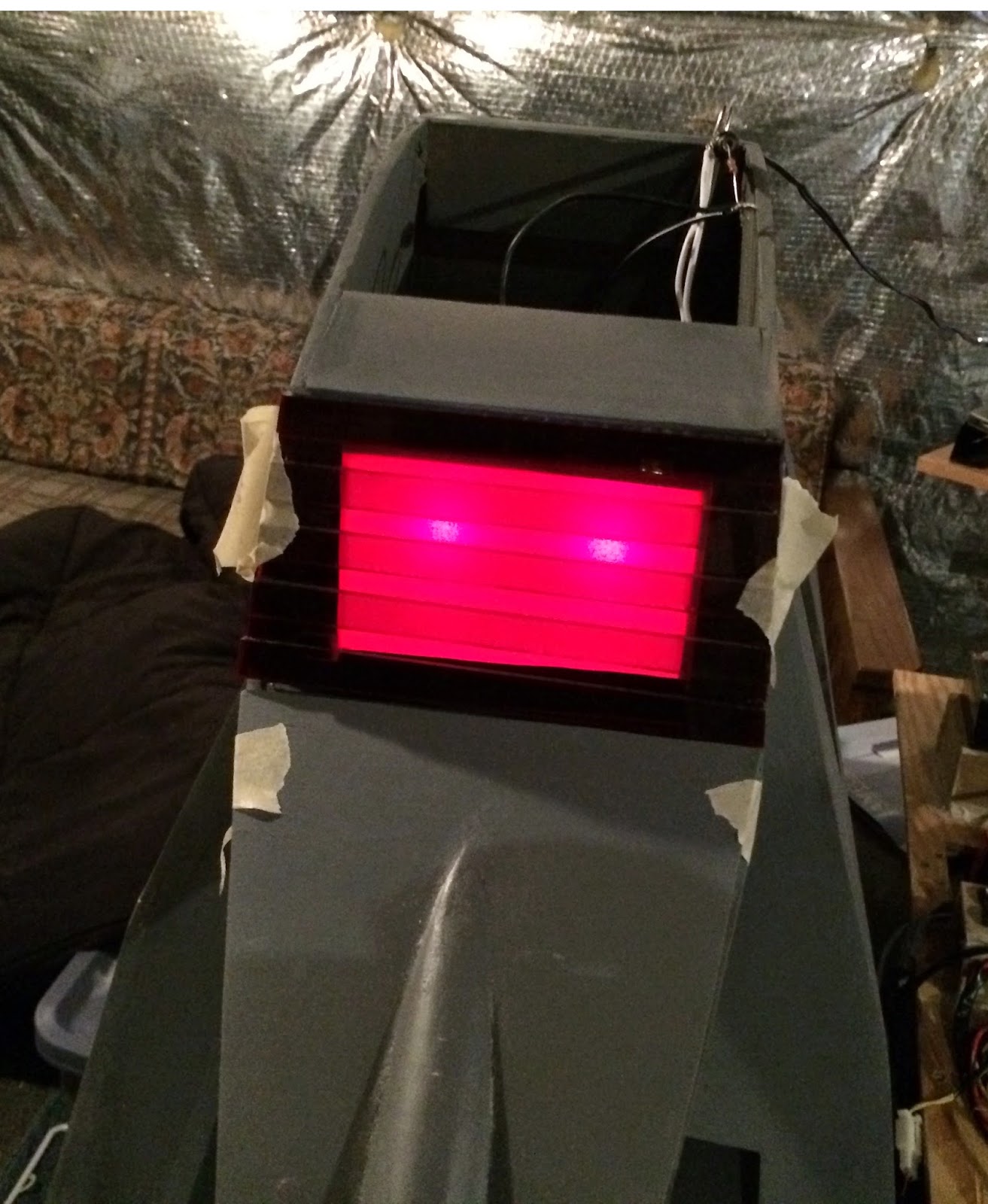
They run fine on 12 volt power and I had two of them. They were perfect for eyes. There are cheeper ways to get LEDs than destroying and expensive, outdoor light fixture, but it all worked out in the end. I built a light box out of white cardboard to house the new eyes. Here is shot of the finished light box.
When I test lit the eyes they looked pretty good. Note that I had to put translucent paper behind the red lens to diffuse the light. Here is what they looked like when I test lit them.
I have made even more progress over the past few months but this entry is getting a little long so I am going to wrap things up. Next up, I will talk about how I relocated the Raspberry PI into the head and installed the electronic antenna and camera into the head as well. For now I will leave you with one more head shot of the completed, telescoping head antenna.
Progress is slow but steady. I am starting to look forward to the software side of this project since the hardware's completion is finally in sight.


1 comment:
Great Post,really it was very helpful for us.
Thanks a lot for sharing!
I found this blog to be very useful!!
Python training in Bangalore
Post a Comment